 Ciro Santilli
This tutorial explains the very basics of how paging works, with focus on x86, although most high level concepts will also apply to other instruction set architectures, e.g. ARM.
The goals are to:
- demonstrate minimal concrete simplified paging examples that will be useful to those learning paging for the first time
- explain the motivation behind paging
This tutorial was extracted and expanded from this Stack Overflow answer.
Minimal example: github.com/cirosantilli/x86-bare-metal-examples/blob/5c672f73884a487414b3e21bd9e579c67cd77621/paging.S
Like everything else in programming, the only way to really understand this is to play with minimal examples.
What makes this a "hard" subject is that the minimal example is large because you need to make your own small OS.
Although it is impossible to understand without examples in mind, try to get familiar with the manuals as soon as possible.
Intel describes paging in the Intel Manual Volume 3 System Programming Guide - 325384-056US September 2015 Chapter 4 "Paging".
Specially interesting is Figure 4-4 "Formats of CR3 and Paging-Structure Entries with 32-Bit Paging", which gives the key data structures.
Paging makes it easier to compile and run two programs or threads at the same time on a single computer.
For example, when you compile two programs, the compiler does not know if they are going to be running at the same time or not.
So nothing prevents it from using the same RAM address, say,
0x1234, to store a global variable.And thread stacks, that must be contiguous and keep growing down until they overwrite each other, are an even bigger issue!
But if two programs use the same address and run at the same time, this is obviously going to break them!
Paging solves this problem beautifully by adding one degree of indirection:
(logical) ------------> (physical)
             paging
Where:
- logical addresses are what userland programs see, e.g. the contents of
rsiinmov eax, [rsi].They are often called "virtual" addresses as well. - physical addresses can be though of the values that go to physical RAM index wires.But keep in mind that this is not 100% true because of further indirections such as:
Compilers don't need to worry about other programs: they just use simple logical addresses.
As far as programs are concerned, they think they can use any address between 0 and 4 GiB (2^32,
FFFFFFFF) on 32-bit systems.The OS then sets up paging so that identical logical addresses will go into different physical addresses and not overwrite each other.
This makes it much simpler to compile programs and run them at the same time.
Paging achieves that goal, and in addition:
- the switch between programs is very fast, because it is implemented by hardware
- the memory of both programs can grow and shrink as needed without too much fragmentation
- one program can never access the memory of another program, even if it wanted to.This is good both for security, and to prevent bugs in one program from crashing other programs.
Or if you like non-funny jokes:

Comparison between the Linux kernel userland memory virtualization and The Matrix
. Source. Is this RAM real?
Paging is implemented by the CPU hardware itself.
Paging could be implemented in software, but that would be too slow, because every single RAM memory access uses it!
Operating systems must setup and control paging by communicating to the CPU hardware. This is done mostly via:
- the CR3 register, which tells the CPU where the page table is in RAM memory
- writing the correct paging data structures to the RAM pointed to the CR3 register.Using RAM data structures is a common technique when lots of data must be transmitted to the CPU as it would cost too much to have such a large CPU register.The format of the configuration data structures is fixed by the hardware, but it is up to the OS to set up and manage those data structures on RAM correctly, and to tell the hardware where to find them (via
cr3).Then some heavy caching is done to ensure that the RAM access will be fast, in particular using the TLB.Another notable example of RAM data structure used by the CPU is the IDT which sets up interrupt handlers.The OS makes it impossible for programs to change the paging setup directly without going through the OS: - CR3 cannot be modified in ring 3. The OS runs in ring 0. See also:
- the page table structures are made invisible to the process using paging itself!
Processes can however make requests to the OS that cause the page tables to be modified, notably:
- stack size changes
brkandmmapcalls, see also: stackoverflow.com/questions/6988487/what-does-brk-system-call-do/31082353#31082353
The kernel then decides if the request will be granted or not in a controlled manner.
In x86 systems, there may actually be 2 address translation steps:like this:
- first segmentation
- then paging
(logical) ------------------> (linear) ------------> (physical)
             segmentation                 paging
The major difference between paging and segmentation is that:
- paging splits RAM into equal sized chunks called pages
- segmentation splits memory into chunks of arbitrary sizes
This is the main advantage of paging, since equal sized chunks make things more manageable by reducing memory fragmentation problems. See also:
Paging came after segmentation historically, and largely replaced it for the implementation of virtual memory in modern OSs.
Paging has become so much more popular that support for segmentation was dropped in x86-64 in 64-bit mode, the main mode of operation for new software, where it only exists in compatibility mode, which emulates IA-32.
This is an example of how paging operates on a simplified version of a x86 architecture to implement a virtual memory space with a
20 | 12 address split (4 KiB page size).This is how the memory could look like in a single level paging scheme:
Links   Data                    Physical address

      +-----------------------+ 2^32 - 1
      |                       |
      .                       .
      |                       |
      +-----------------------+ page0 + 4k
      | data of page 0        |
+---->+-----------------------+ page0
|     |                       |
|     .                       .
|     |                       |
|     +-----------------------+ pageN + 4k
|     | data of page N        |
|  +->+-----------------------+ pageN
|  |  |                       |
|  |  .                       .
|  |  |                       |
|  |  +-----------------------+ CR3 + 2^20 * 4
|  +--| entry[2^20-1] = pageN |
|     +-----------------------+ CR3 + 2^20 - 1 * 4
|     |                       |
|     .    many entires       .
|     |                       |
|     +-----------------------+ CR3 + 2 * 4
|  +--| entry[1] = page1      |
|  |  +-----------------------+ CR3 + 1 * 4
+-----| entry[0] = page0      |
   |  +-----------------------+ <--- CR3
   |  |                       |
   |  .                       .
   |  |                       |
   |  +-----------------------+ page1 + 4k
   |  | data of page 1        |
   +->+-----------------------+ page1
      |                       |
      .                       .
      |                       |
      +-----------------------+  0
Notice that:
- the CR3 register points to the first entry of the page table
- the page table is just a large array with 2^20 page table entries
- each entry is 4 bytes big, so the array takes up 4 MiB
- each page table contains the physical address a page
- each page is a 4 KiB aligned 4 KiB chunk of memory that user processes may use
- we have 2^20 table entries. Since each page is 4 KiB == 2^12, this covers the whole 4 GiB (2^32) of 32-bit memory
Suppose that the OS has setup the following page tables for process 1:and for process 2:
entry index   entry address       page address   present
-----------   ------------------  ------------   -------
0             CR3_1 + 0      * 4  0x00001        1
1             CR3_1 + 1      * 4  0x00000        1
2             CR3_1 + 2      * 4  0x00003        1
3             CR3_1 + 3      * 4                 0
...
2^20-1 CR3_1 + 2^20-1 * 4 0x00005 1entry index entry address page address present
----------- ----------------- ------------ -------
0 CR3_2 + 0 * 4 0x0000A 1
1 CR3_2 + 1 * 4 0x12345 1
2 CR3_2 + 2 * 4 0
3 CR3_2 + 3 * 4 0x00003 1
...
2^20-1 CR3_2 + 2^20-1 * 4 0xFFFFF 1Before process 1 starts running, the OS sets its
cr3 to point to the page table 1 at CR3_1.When process 1 tries to access a linear address, this is the physical addresses that will be actually accessed:
linear     physical
---------  ---------
00000 001  00001 001
00000 002  00001 002
00000 003  00001 003
00000 FFF  00001 FFF
00001 000  00000 000
00001 001  00000 001
00001 FFF  00000 FFF
00002 000  00003 000
FFFFF 000  00005 000
To switch to process 2, the OS simply sets
cr3 to CR3_2, and now the following translations would happen:linear physical
--------- ---------
00000 002 0000A 002
00000 003 0000A 003
00000 FFF 0000A FFF
00001 000 12345 000
00001 001 12345 001
00001 FFF 12345 FFF
00004 000 00003 000
FFFFF 000 FFFFF 000Step-by-step translation for process 1 of logical address
0x00000001 to physical address 0x00001001:- split the linear address into two parts:
| page (20 bits) | offset (12 bits) |So in this case we would have:
*page = 0x00000. This part must be translated to a physical location.
*offset = 0x001. This part is added directly to the page address, and is not translated: it contains the position within the page. - look into Page table 1 because
cr3points to it. - The hardware knows that this entry is located at RAM address
CR3 + 0x00000 * 4 = CR3:
*0x00000because the page part of the logical address is0x00000
*4because that is the fixed size in bytes of every page table entry - since it is present, the access is valid
- by the page table, the location of page number
0x00000is at0x00001 * 4K = 0x00001000. - to find the final physical address we just need to add the offset:
00001 000 + 00000 001 --------- 00001 001because00001is the physical address of the page looked up on the table and001is the offset.We shift00001by 12 bits because the pages are always aligned to 4 KiB.The offset is always simply added the physical address of the page. - the hardware then gets the memory at that physical location and puts it in a register.
Another example: for logical address
0x00001001:- the page part is
00001, and the offset part is001 - the hardware knows that its page table entry is located at RAM address:
CR3 + 1 * 4(1because of the page part), and that is where it will look for it - it finds the page address
0x00000there - so the final address is
0x00000 * 4k + 0x001 = 0x00000001
The same linear address can translate to different physical addresses for different processes, depending only on the value inside
cr3.Both linear addresses
00002 000 from process 1 and 00004 000 from process 2 point to the same physical address 00003 000. This is completely allowed by the hardware, and it is up to the operating system to handle such cases.This often in normal operation because of Copy-on-write (COW), which be explained elsewhere.
Such mappings are sometime called "aliases".
FFFFF 000 points to its own physical address FFFFF 000. This kind of translation is called an "identity mapping", and can be very convenient for OS-level debugging.What if Process 1 tries to access
0x00003000, which is not present?The hardware notifies the software via a Page Fault Exception.
When an exception happens, the CPU jumps to an address that the OS had previously registered as the fault handler. This is usually done at boot time by the OS.
This could happen for example due to a programming error:but there are cases where it is not a bug, for example in Linux when:
int *is = malloc(1);
is[2] = 1;- the program wants to increase its stack.It just tries to accesses a certain byte in a given possible range, and if the OS is happy it adds that page to the process address space, otherwise, it sends a signal to the process.
- the page was swapped to disk.The OS will need to do some work behind the processes back to get the page back into RAM.The OS can discover that this is the case based on the contents of the rest of the page table entry, since if the present flag is clear, the other entries of the page table entry are completely left for the OS to to what it wants.On Linux for example, when present = 0:
- if all the fields of the page table entry are 0, invalid address.
- else, the page has been swapped to disk, and the actual values of those fields encode the position of the page on the disk.
In any case, the OS needs to know which address generated the Page Fault to be able to deal with the problem. This is why the nice IA32 developers set the value of
cr2 to that address whenever a Page Fault occurs. The exception handler can then just look into cr2 to get the address.The exact format of table entries is fixed by the hardware.
Each page entry can be seen as a
struct with many fields.The page table is then an array of
struct.On this simplified example, the page table entries contain only two fields:so in this example the hardware designers could have chosen the size of the page table to b
bits   function
-----  -----------------------------------------
20     physical address of the start of the page
1 present flag21 instead of 32 as we've used so far.All real page table entries have other fields, notably fields to set pages to read-only for Copy-on-write. This will be explained elsewhere.
It would be impractical to align things at 21 bits since memory is addressable by bytes and not bits. Therefore, even in only 21 bits are needed in this case, hardware designers would probably choose 32 to make access faster, and just reserve bits the remaining bits for later usage. The actual value on x86 is 32 bits.
Here is a screenshot from the Intel manual image "Formats of CR3 and Paging-Structure Entries with 32-Bit Paging" showing the structure of a page table in all its glory: Figure 2. "x86 page entry format".
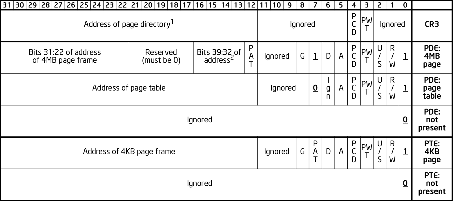
x86 page entry format
. The fields are explained in the manual just after.
Why are pages 4 KiB anyways?
There is a trade-off between memory wasted in:
- page tables
- extra padding memory within pages
This can be seen with the extreme cases:
- if the page size were 1 byte:
- granularity would be great, and the OS would never have to allocate unneeded padding memory
- but the page table would have 2^32 entries, and take up the entire memory!
- if the page size were 4 GiB:
- we would need to swap 4 GiB to disk every time a new process becomes active
- the page size would be a single entry, so it would take almost no memory at all
x86 designers have found that 4 KiB pages are a good middle ground.
The problem with a single-level paging scheme is that it would take up too much RAM: 4G / 4K = 1M entries per process.
If each entry is 4 bytes long, that would make 4M per process, which is too much even for a desktop computer:
ps -A | wc -l says that I am running 244 processes right now, so that would take around 1GB of my RAM!For this reason, x86 developers decided to use a multi-level scheme that reduces RAM usage.
The downside of this system is that is has a slightly higher access time, as we need to access RAM more times for each translation.
The algorithmically minded will have noticed that paging requires associative array (like Java
Map of Python dict()) abstract data structure where:- the keys are linear pages addresses, thus of integer type
- the values are physical page addresses, also of integer type
The single level paging scheme uses a simple array implementation of the associative array:and in C pseudo-code it looks like this:
- the keys are the array index
- this implementation is very fast in time
- but it is too inefficient in memory
linear_address[0]      = physical_address_0
linear_address[1]      = physical_address_1
linear_address[2]      = physical_address_2
...
linear_address[2^20-1] = physical_address_N
But there another simple associative array implementation that overcomes the memory problem: an (unbalanced) k-ary tree.
A K-ary tree, is just like a binary tree, but with K children instead of 2.
Using a K-ary tree instead of an array implementation has the following trade-offs:
- it uses way less memory
- it is slower since we have to de-reference extra pointers
In C-pseudo code, a 2-level K-ary tree with and we have the following arrays:and it still contains
K = 2^10 looks like this:level0[0] = &level1_0[0]
level1_0[0] = physical_address_0_0
level1_0[1] = physical_address_0_1
...
level1_0[2^10-1] = physical_address_0_N
level0[1] = &level1_1[0]
level1_1[0] = physical_address_1_0
level1_1[1] = physical_address_1_1
...
level1_1[2^10-1] = physical_address_1_N
...
level0[N] = &level1_N[0]
level1_N[0] = physical_address_N_0
level1_N[1] = physical_address_N_1
...
level1_N[2^10-1] = physical_address_N_N- one
directory, which has2^10elements. Each element contains a pointer to a page table array. - up to 2^10
pagetablearrays. Each one has2^104 byte page entries.
2^10 * 2^10 = 2^20 possible keys.K-ary trees can save up a lot of space, because if we only have one key, then we only need the following arrays:
- one
directorywith 2^10 entries - one
pagetableatdirectory[0]with 2^10 entries - all other
directory[i]are marked as invalid, don't point to anything, and we don't allocatepagetablefor them at all
Learned readers will ask themselves: so why use an unbalanced tree instead of balanced one, which offers better asymptotic times en.wikipedia.org/wiki/Self-balancing_binary_search_tree?
Likely:
- the maximum number of entries is small enough due to memory size limitations, that we won't waste too much memory with the root directory entry
- different entries would have different levels, and thus different access times
- tree rotations would likely make caching more complicated
x86's multi-level paging scheme uses a 2 level K-ary tree with 2^10 bits on each level.
Addresses are now split as:
| directory (10 bits) | table (10 bits) | offset (12 bits) |Then:
- the top 10 bits are used to walk the top level of the K-ary tree (
level0)The top table is called a "directory of page tables".cr3now points to the location on RAM of the page directory of the current process instead of page tables.Page directory entries are very similar to page table entries except that they point to the physical addresses of page tables instead of physical addresses of pages.Each directory entry also takes up 4 bytes, just like page entries, so that makes 4 KiB per process minimum.Page directory entries also contain a valid flag: if invalid, the OS does not allocate a page table for that entry, and saves memory.Each process has one and only one page directory associated to it (and pointed to bycr3), so it will contain at least2^10 = 1Kpage directory entries, much better than the minimum 1M entries required on a single-level scheme. - the next 10 bits are used to walk the second level of the K-ary tree (
level1)Second level entries are also called page tables like the single level scheme.Page tables are only allocated only as needed by the OS.Each page table has only2^10 = 1Kpage table entries instead of2^20for the single paging scheme.Each process can now have up to2^10page tables instead of2^20for the single paging scheme. - the offset is again not used for translation, it only gives the offset within a page
One reason for using 10 bits on the first two levels (and not, say,
12 | 8 | 12 ) is that each Page Table entry is 4 bytes long. Then the 2^10 entries of Page directories and Page Tables will fit nicely into 4Kb pages. This means that it faster and simpler to allocate and deallocate pages for that purpose.Page directory given to process by the OS:
entry index   entry address      page table address  present
-----------   ----------------   ------------------  --------
0             CR3 + 0      * 4   0x10000             1
1             CR3 + 1      * 4                       0
2             CR3 + 2      * 4   0x80000             1
3             CR3 + 3      * 4                       0
...
2^10-1        CR3 + 2^10-1 * 4                       0
Page tables given to process by the OS at
PT1 = 0x10000000 (0x10000 * 4K):entry index entry address page address present
----------- ---------------- ------------ -------
0 PT1 + 0 * 4 0x00001 1
1 PT1 + 1 * 4 0
2 PT1 + 2 * 4 0x0000D 1
... ...
2^10-1 PT1 + 2^10-1 * 4 0x00005 1Page tables given to process by the OS at where
PT2 = 0x80000000 (0x80000 * 4K):entry index entry address page address present
----------- --------------- ------------ ------------
0 PT2 + 0 * 4 0x0000A 1
1 PT2 + 1 * 4 0x0000C 1
2 PT2 + 2 * 4 0
...
2^10-1 PT2 + 0x3FF * 4 0x00003 1PT1 and PT2: initial position of page table 1 and page table 2 for process 1 on RAM.With that setup, the following translations would happen:
linear    10 10 12 split  physical
--------  --------------  ----------
00000001  000 000 001     00001001
00001001  000 001 001     page fault
003FF001  000 3FF 001     00005001
00400000  001 000 000     page fault
00800001  002 000 001     0000A001
00801004  002 001 004     0000C004
00802004  002 002 004     page fault
00B00001  003 000 000     page fault
Let's translate the linear address
0x00801004 step by step:- In binary the linear address is:
0 0 8 0 1 0 0 4 0000 0000 1000 0000 0001 0000 0000 0100 - Grouping as
10 | 10 | 12gives:which gives:0000000010 0000000001 000000000100 0x2 0x1 0x4So the hardware looks for entry 2 of the page directory.page directory entry = 0x2 page table entry = 0x1 offset = 0x4 - The page directory table says that the page table is located at
0x80000 * 4K = 0x80000000. This is the first RAM access of the process.Since the page table entry is0x1, the hardware looks at entry 1 of the page table at0x80000000, which tells it that the physical page is located at address0x0000C * 4K = 0x0000C000. This is the second RAM access of the process. - Finally, the paging hardware adds the offset, and the final address is
0x0000C004.
Page faults occur if either a page directory entry or a page table entry is not present.
The Intel manual gives a picture of this translation process in the image "Linear-Address Translation to a 4-KByte Page using 32-Bit Paging": Figure 3. "x86 page translation process"
x86 page translation process
. 64 bits is still too much address for current RAM sizes, so most architectures will use less bits.
x86_64 uses 48 bits (256 TiB), and legacy mode's PAE already allows 52-bit addresses (4 PiB). 56-bits is a likely future candidate.
12 of those 48 bits are already reserved for the offset, which leaves 36 bits.
If a 2 level approach is taken, the best split would be two 18 bit levels.
But that would mean that the page directory would have
2^18 = 256K entries, which would take too much RAM: close to a single-level paging for 32 bit architectures!Therefore, 64 bit architectures create even further page levels, commonly 3 or 4.
x86_64 uses 4 levels in a
9 | 9 | 9 | 9 scheme, so that the upper level only takes up only 2^9 higher level entries.The 48 bits are split equally into two disjoint parts:
----------------- FFFFFFFF FFFFFFFF
Top half
----------------- FFFF8000 00000000


Not addressable


----------------- 00007FFF FFFFFFFF
Bottom half
----------------- 00000000 00000000
A 5-level scheme is emerging in 2016: software.intel.com/sites/default/files/managed/2b/80/5-level_paging_white_paper.pdf which allows 52-bit addresses with 4k pagetables.
Physical address extension.
With 32 bits, only 4GB RAM can be addressed.
This started becoming a limitation for large servers, so Intel introduced the PAE mechanism to Pentium Pro.
To relieve the problem, Intel added 4 new address lines, so that 64GB could be addressed.
Page table structure is also altered if PAE is on. The exact way in which it is altered depends on weather PSE is on or off.
PAE is turned on and off via the
PAE bit of cr4.Even if the total addressable memory is 64GB, individual process are still only able to use up to 4GB. The OS can however put different processes on different 4GB chunks.
Page size extension.
Allows for pages to be 4M (or 2M if PAE is on) in length instead of 4K.
PSE is turned on and off via the
PSE bit of cr4.If either PAE and PSE are active, different paging level schemes are used:
- no PAE and no PSE:
10 | 10 | 12 - no PAE and PSE:
10 | 22.22 is the offset within the 4Mb page, since 22 bits address 4Mb. - PAE and no PSE:
2 | 9 | 9 | 12The design reason why 9 is used twice instead of 10 is that now entries cannot fit anymore into 32 bits, which were all filled up by 20 address bits and 12 meaningful or reserved flag bits.The reason is that 20 bits are not enough anymore to represent the address of page tables: 24 bits are now needed because of the 4 extra wires added to the processor.Therefore, the designers decided to increase entry size to 64 bits, and to make them fit into a single page table it is necessary reduce the number of entries to 2^9 instead of 2^10.The starting 2 is a new Page level called Page Directory Pointer Table (PDPT), since it points to page directories and fill in the 32 bit linear address. PDPTs are also 64 bits wide.cr3now points to PDPTs which must be on the fist four 4GB of memory and aligned on 32 bit multiples for addressing efficiency. This means that nowcr3has 27 significative bits instead of 20: 2^5 for the 32 multiples * 2^27 to complete the 2^32 of the first 4GB. - PAE and PSE:
2 | 9 | 21Designers decided to keep a 9 bit wide field to make it fit into a single page.This leaves 23 bits. Leaving 2 for the PDPT to keep things uniform with the PAE case without PSE leaves 21 for offset, meaning that pages are 2M wide instead of 4M.
The Translation Lookahead Buffer (TLB) is a cache for paging addresses.
Since it is a cache, it shares many of the design issues of the CPU cache, such as associativity level.
This section shall describe a simplified fully associative TLB with 4 single address entries. Note that like other caches, real TLBs are not usually fully associative.
After a translation between linear and physical address happens, it is stored on the TLB. For example, a 4 entry TLB starts in the following state:
  valid  linear  physical
  -----  ------  --------
> 0      00000   00000
  0      00000   00000
  0      00000   00000
  0      00000   00000
The
> indicates the current entry to be replaced.And after a page linear address and after a second translation of
00003 is translated to a physical address 00005, the TLB becomes: valid linear physical
----- ------ --------
1 00003 00005
> 0 00000 00000
0 00000 00000
0 00000 0000000007 to 00009 it becomes: valid linear physical
----- ------ --------
1 00003 00005
1 00007 00009
> 0 00000 00000
0 00000 00000Now if
00003 needs to be translated again, hardware first looks up the TLB and finds out its address with a single RAM access 00003 --> 00005.Of course,
00000 is not on the TLB since no valid entry contains 00000 as a key.When TLB is filled up, older addresses are overwritten. Just like CPU cache, the replacement policy is a potentially complex operation, but a simple and reasonable heuristic is to remove the least recently used entry (LRU).
With LRU, starting from state:adding
  valid  linear  physical
  -----  ------  --------
> 1      00003   00005
  1      00007   00009
  1      00009   00001
1 0000B 000030000D -> 0000A would give: valid linear physical
----- ------ --------
1 0000D 0000A
> 1 00007 00009
1 00009 00001
1 0000B 00003Using the TLB makes translation faster, because the initial translation takes one access per TLB level, which means 2 on a simple 32 bit scheme, but 3 or 4 on 64 bit architectures.
The TLB is usually implemented as an expensive type of RAM called content-addressable memory (CAM). CAM implements an associative map on hardware, that is, a structure that given a key (linear address), retrieves a value.
Mappings could also be implemented on RAM addresses, but CAM mappings may required much less entries than a RAM mapping.
For example, a map in which:could be stored in a TLB with 4 entries:
- both keys and values have 20 bits (the case of a simple paging schemes)
- at most 4 values need to be stored at each time
linear  physical
------  --------
00000   00001
00001   00010
00010   00011
FFFFF   00000
However, to implement this with RAM, it would be necessary to have 2^20 addresses:which would be even more expensive than using a TLB.
linear  physical
------  --------
00000   00001
00001   00010
00010   00011
... (from 00011 to FFFFE)
FFFFF 00000When the process changes,
cr3 change to point to the page table of the new current process.This creates a problem: the TLB is now filled with a bunch of cached entries for the old process.
A simple and naive solution would be to completely invalidate the TLB whenever the
cr3 changes.However, this is would not be very efficient, because it often happens that we switch back to process 1 before process 2 has completely used up the entire TLB cache entries.
The solution for this is to use so called "Address Space Identifiers" (ASID) as mentioned in sources such as:
Basically, the OS assigns a different ASID for each process, and then TLB entries are automatically also tagged with that ASID. This way when the process makes an access, the TLB can determine if a hit is actually for the current process, or if it is an old address coincidence with another process.
The x86 also offers the
invlpg instruction which explicitly invalidates a single TLB entry. Other architectures offer even more instructions to invalidated TLB entries, such as invalidating all entries on a given range.The Linux kernel makes extensive usage of the paging features of x86 to allow fast process switches with small data fragmentation.
There are also however some features that the Linux kernel might not use, either because they are only for backwards compatibility, or because the Linux devs didn't feel it was worth it yet.
Convert virtual addresses to physical from user space with
/proc/<pid>/pagemap and from kernel space with virt_to_phys:Dump all page tables from userspace with
/proc/<pid>/maps and /proc/<pid>/pagemap:Read and write physical addresses from userspace with
/dev/mem:The Linux Kernel reserves two zones of virtual memory:
- one for kernel memory
- one for programs
The exact split is configured by
CONFIG_VMSPLIT_.... By default:- on 32-bit:
- the bottom 3/4 is program space:
00000000toBFFFFFFF - the top 1/4 is kernel memory:
C0000000toFFFFFFFF, like this:------------------ FFFFFFFF Kernel ------------------ C0000000 ------------------ BFFFFFFF Process ------------------ 00000000
- the bottom 3/4 is program space:
- on 64-bit: currently only 48-bits are actually used, split into two equally sized disjoint spaces. The Linux kernel just assigns:
- the bottom part to processes
00000000 00000000to008FFFFF FFFFFFFF - the top part to the kernel:
FFFF8000 00000000toFFFFFFFF FFFFFFFF, like this:------------------ FFFFFFFF Kernel ------------------ C0000000 (not addressable) ------------------ BFFFFFFF Process ------------------ 00000000
- the bottom part to processes
Kernel memory is also paged.
In previous versions, the paging was continuous, but with HIGHMEM this changed.
There is no clear physical memory split: stackoverflow.com/questions/30471742/physical-memory-userspace-kernel-split-on-linux-x86-64
For each process, the virtual address space looks like this:
------------------ 2^32 - 1
Stack (grows down)
v v v v v v v v v
------------------

(unmapped)

------------------ Maximum stack size.


(unmapped)


-------------------
mmap
-------------------


(unmapped)


-------------------
^^^^^^^^^^^^^^^^^^^
brk (grows up)
-------------------
BSS
-------------------
Data
-------------------
Text
-------------------

------------------- 0
The kernel maintains a list of pages that belong to each process, and synchronizes that with the paging.
If the program accesses memory that does not belong to it, the kernel handles a page-fault, and decides what to do:
- if it is above the maximum stack size, allocate those pages to the process
- otherwise, send a SIGSEGV to the process, which usually kills it
When an ELF file is loaded by the kernel to start a program with the
exec system call, the kernel automatically registers text, data, BSS and stack for the program.The
brk and mmap areas can be modified by request of the program through the brk and mmap system calls. But the kernel can also deny the program those areas if there is not enough memory.brk and mmap can be used to implement malloc, or the so called "heap".mmap is also used to load dynamically loaded libraries into the program's memory so that it can access and run it.Stack allocation: stackoverflow.com/questions/17671423/stack-allocation-for-process
Calculating exact addresses Things are complicated by:
- Address Space Layout Randomization.
- the fact that environment variables, CLI arguments, and some ELF header data take up initial stack space: unix.stackexchange.com/questions/145557/how-does-stack-allocation-work-in-linux/239323#239323
Why the text does not start at 0: stackoverflow.com/questions/14795164/why-do-linux-program-text-sections-start-at-0x0804800-and-stack-tops-start-at-0
Besides a missing page, a very common source of page faults is copy-on-write (COW).
Page tables have extra flags that allow the OS to mark a page a read-only.
Those page faults only happen when a process tries to write to the page, and not read from it.
When Linux forks a process:
- instead of copying all the pages, which is unnecessarily costly, it makes the page tables of the two process point to the same physical address.
- it marks those linear addresses as read-only
- whenever one of the processes tries to write to a page, the makes a copy of the physical memory, and updates the pages of the two process to point to the two different physical addresses
In
v4.2, look under arch/x86/:include/asm/pgtable*include/asm/page*mm/pgtable*mm/page*
There seems to be no structs defined to represent the pages, only macros:
include/asm/page_types.h is specially interesting. Excerpt:#define _PAGE_BIT_PRESENT 0 /* is present */
#define _PAGE_BIT_RW 1 /* writeable */
#define _PAGE_BIT_USER 2 /* userspace addressable */
#define _PAGE_BIT_PWT 3 /* page write through */arch/x86/include/uapi/asm/processor-flags.h defines CR0, and in particular the PG bit position:#define X86_CR0_PG_BIT 31 /* Paging */Paging is done by the Memory Management Unit (MMU) part of the CPU.
Like many others (e.g. x87 co-processor, APIC), this used to be by separate chip on early days.
It was later integrated into the CPU, but the term MMU still used.
Two level address translation to make OS emulation more efficient.
Peter Cordes mentions that some architectures like MIPS leave paging almost completely in the hands of software: a TLB miss runs an OS-supplied function to walk the page tables, and insert the new mapping into the TLB. In such architectures, the OS can use whatever data structure it wants.
Information about ARM paging can be found at: cirosantilli.com/linux-kernel-module-cheat#arm-paging
Free:
- rutgers-pxk-416 chapter "Memory management: lecture notes"Good historical review of memory organization techniques used by older OS.
Non-free:
- bovet05 chapter "Memory addressing"Reasonable intro to x86 memory addressing. Missing some good and simple examples.